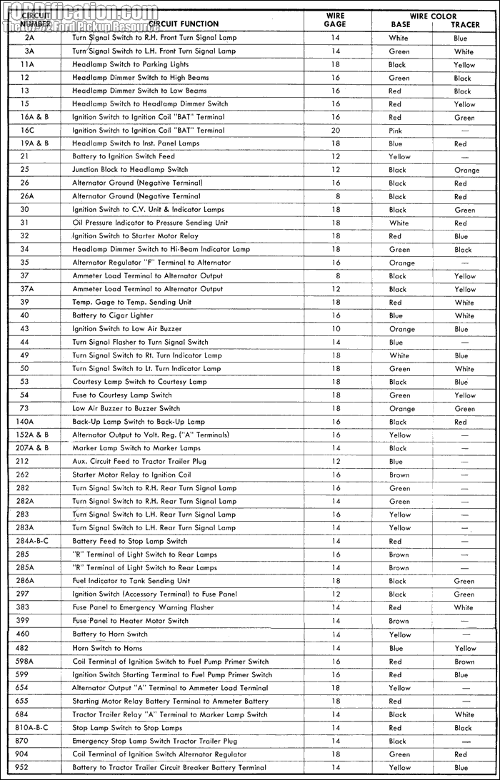
I have a 1971 F250 RANGER XLT in the 20,000 serial range. My turn signal switch has been a nightmare. Signals stopped working and old one was bad. I bought replacement but colors don't match. They gave me a cross reference chart for new colors for pinout, but I am blowing fuses with Brake and turn signals don't work. I know it's in the switch, but can't figure out what goes where. I have triple checked and everything is correct according to their chart. I even took to mechanic and electrical place and neither one could figure it out.
Does anyone one have details or diagram for what each wire would do on the turn signal switch? I tried with my multi-meter and can't figure it out. If I could, I could make sure they are correct to factory plug.
Any help or pointers are appreciated. Thanks in Advance!
Here are pics of plug and column water -
https://drive.google.com/drive/folders/ ... sp=sharing


